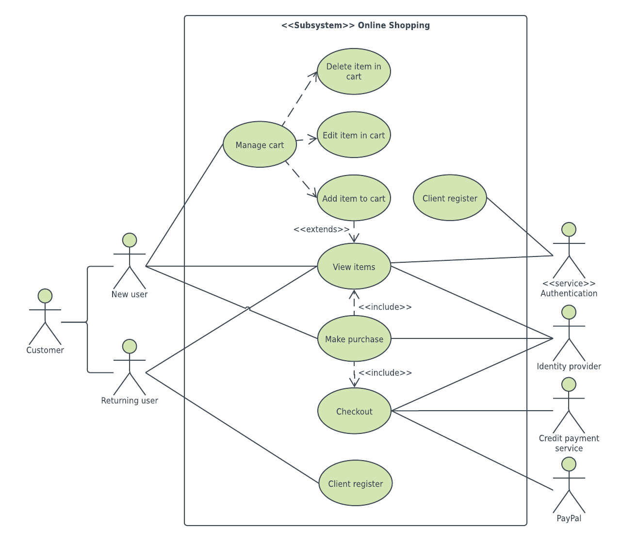
Notation of System Boundary (Subject) is a rectangle with System’s name on top of the rectangle.Īll use cases or functionality of the specific system are located inside the rectangle. It details a set of actions between actors and the data consumed and produced if any. #1) System: It is also referred to as scenario or functionality. Listed below are some important components of Use Case diagrams:

The key development activity status enables the project heads to present the readiness from a customer deliverable point of view.
ONLINE USE CASE DIAGRAM VERIFICATION

The diagrams do not give the details of deployment, trigger of the event, etc. It also presents the functionality’s exceptions, pre-condition, and post-condition. The observable outcome of the functionality to the actor and other stakeholders of the system is shown with clarity.

It represented the collaboration and interdependence of the functionality and users in a very easy and understandable manner. The presentation is from the perspective of all users giving a high-level design and basic flow of events of the system. The main purpose is to present all functional requirements of the system diagrammatically with all the users who can access the functionality. Hence multiple use case diagrams represent the complete system. For every single functionality representation, a fresh diagram is used. design, implementation, process, and deployment. Use Case diagram represents the system’s functionality connecting all four perspectives, i.e.


 0 kommentar(er)
